Showing posts with label Tools. Show all posts

Friday, 17 April 2026

Dress for the Job You Want

Where do you see yourself in five years time?

If the answer is Chief Warlord to a crew of Mutant Wasteland Marauders in a Peri-Apocalyptic hellscape, well maybe you need one of these...

Mercenary Garage Custom Motorcycle Workshop Warlord Schrade Dual Survival Knife Setup Wolverine Leroy Firesteel Wasteland Peri-Apocalyptic Hellscape

Mercenary Garage Custom Motorcycle Workshop Warlord Schrade Dual Survival Knife Setup Wolverine Leroy Firesteel Wasteland Peri-Apocalyptic Hellscape

Mercenary Garage Custom Motorcycle Workshop Warlord Schrade Dual Survival Knife Setup Wolverine Leroy Firesteel Wasteland Peri-Apocalyptic Hellscape

Mercenary Garage Custom Motorcycle Workshop Warlord Schrade Dual Survival Knife Setup Wolverine Leroy Firesteel Wasteland Peri-Apocalyptic Hellscape

Mercenary Garage Custom Motorcycle Workshop Warlord Schrade Dual Survival Knife Setup Wolverine Leroy Firesteel Wasteland Peri-Apocalyptic Hellscape

Remember, dress for the job you want!


Images - Mercenary Garage


#Schrade #SchradeWolverine #SchradeLeroy #SchradeDualKnife #SurvivalKnife #DualSurvivalKnives #PeriApocalypse #PostApocalypse #Apocalypse #Warlord #Wasteland #ApocalypseKnife #Mercenary #MercenaryMotorcycles #MercenaryGarage #WastelandWarlord

Tuesday, 12 August 2025

Chekhov's Power Loader

It was fortunate that Ripley had her Class 2 Rating to operate that Caterpillar P-5000 Powered Work Loader. 

Jus' sayin'...

Mercenary Garage Custom Motorcycle Workshop 1986 Aliens Sigourny Weaver Ellen Ripley WY Weyland Yutani  Cat Caterpillar P-5000 Powered Work LoaderCyberpunk Dystopia Building better Worlds


Image - Aliens (1986)


#Aliens #ChekhovsGun #WeylandYutani #Caterpillar #PowerLoader #Mercenary #MercenaryMotorcycles #MercenaryGarage

Saturday, 15 June 2024

The KLF

Mercenary Garage Custom Motorcycle Workshop 1990s The KLF Jim Cauty and Bill Drummond Angle Grinders


Image - Unknown


#KLF #TheKLF #JAMM #AngleGrinder #Mercenary #MercenaryMotorcycles #MercenaryGarage

Thursday, 1 September 2022

Got Zombie?

Tactical Zombie Hunting on a Surron-X Electric Enduro Dirt Bike - Note Tactical Sawzall Side-arm


Image - via ThePictureTaker on Instagram*


#SurronX #ElectricEnduroBike #Camouflage #ZombieHunter #GotZombie #TacticalShiz #Mercenary #MercenaryMotorcycles #MercenaryGarage

*It's not clear to me if the Picture Taker took the picture or y'know, took the picture. But credit where credit is due... 

Tuesday, 23 August 2022

Sparks

The sparks, they make it look legit. - Thor Drake, See See Motorcycles


Image - https://sjenterprises.co.uk


#AngleGrinder #AngleGrinderPerformance #Mercenary #MercenaryMotorcycles #MercenaryGarage 

Monday, 31 May 2021

Mercenary Ghetto Engineering

So one of my courier buddies, Alan arrived out at the workshop yesterday with a couple of cylinders from a Lambretta GP200 and a crankcase from a Lambretta GP150, to do some machining.

Apparently fitting 200 barrels to 150 cases is a desirable modification in Lambretta circles, but it's not quite a bolt up operation. The difficulty is that the bottom of the 200 cylinder (the skirt) has an outside diameter of 75 mm and the 150 crankcase mouth has a diameter of 70mm. So something's got to give.

The conventional wisdom would suggest that the right way to do this would be to enlarge the 70 mm diameter crankcase mouth to 75 mm. 

However the crankcase is an irregular shape and it's pretty big. That single casting is also the swingarm, the brake hub, the suspension mount and the wheel... eh... holder. There is also Dog-knows-what kind of transmission system in there too. 

Anyway, I'm guessing it requires some specialist fixture to hold the thing and line boring equipment to do the operation. Also, there is a sort of shoulder at the bottom of the mouth that would prevent enlarging the mouth by hand with a file which otherwise is something I would definitely do.

In addition to this, enlarging the crank mouth reduces the amount of metal around the cylinder studs and requires a further series of modifications to remedy. There are Lambretta specialists in the UK that do this operation but it's understandably expensive. And since Brexit a couple of months back, this kind of trade between the UK and Ireland now incurs taxes on the goods or services and additional taxes on the shipping which makes it prohibitively expensive. Such is life.

So, that's why we went ghetto.

Weirdly, the DRO was malfunctioning so we did it old-school with dial gauges which is even more ghetto. The DRO seems to be working happily again now. Dunno.

We stuck the 200 barrels into the lathe and took 2.5 mm off the radius. The skirts were made of cast iron which is lovely to machine and gives a nice surface finish. It seemed to work pretty well and Alan was happy with the finished products. 

Now, in my defense, according to Alan this type of conversion has been going on in Ireland since the '80s and it came about because it's a more robust than boring out a 150 barrel to take a 200 piston which was supposedly fragile. 

So this may not the ideal way to approach this, but it works. 

In the words of Mikhail Kalashnikov - "Perfection is the enemy of good enough".


This is what serves as a crankcase on a scooter. The big roundy bit at the front is where the crank goes. The big roundy bit at the back is the brake hub. I'm pretty sure the horizontal hole is for carrying a refreshing non-alcoholic beverage.
This is what serves as a crankcase on a scooter. The big roundy bit at the front is where the crank goes. The big roundy bit at the back is the brake hub. I'm pretty sure the horizontal hole is a beverage holder.


This is the mouth of the crankcase. It's easy to see that enlarging the hole by 5 mm is going to compromise the cylinder stud mounts. And it's clear that enlarging it by hand is prohibitively difficult.
This is the mouth of the crankcase. It's easy to see that enlarging the hole by 5 mm is going to compromise the cylinder stud mounts. And it's clear that enlarging it by hand is not really possible.


Before (left) and after shot showing a modified and unmodified Lambretta GP200 cylinder.
Before (left) and after shot comparing a modified and unmodified Lambretta GP200 cylinder.


Checking the run-out of the barrel in the lathe using a dial-gauge.


Work in progress. Machining cast-iron is lovely.


Closeup of the finished piece.
Closeup of the finished piece. 


Ducks in a row...


#Lambretta #LambrettaGP200 #LambrettaGP150 #OldSkool #OldSchool #Ghetto #GhettoEngineering #PerfectionIsTheEnemyOfGoodEnough #MercenaryEngineering #MercenaryMotorcycleWorkshop #MercenaryMotorcycles #Mercenary #MercenaryGarage


Monday, 7 December 2020

Honda VTR1000 SP1 to SP2 Swing-arm Conversion

Ro's SP1 about to go under the knife.


So a couple of weeks ago, Ro brought his Honda VTR 1000 SP1 out to the 'shop to swap out the swing-arm for the swing-arm off a later SP2 model.

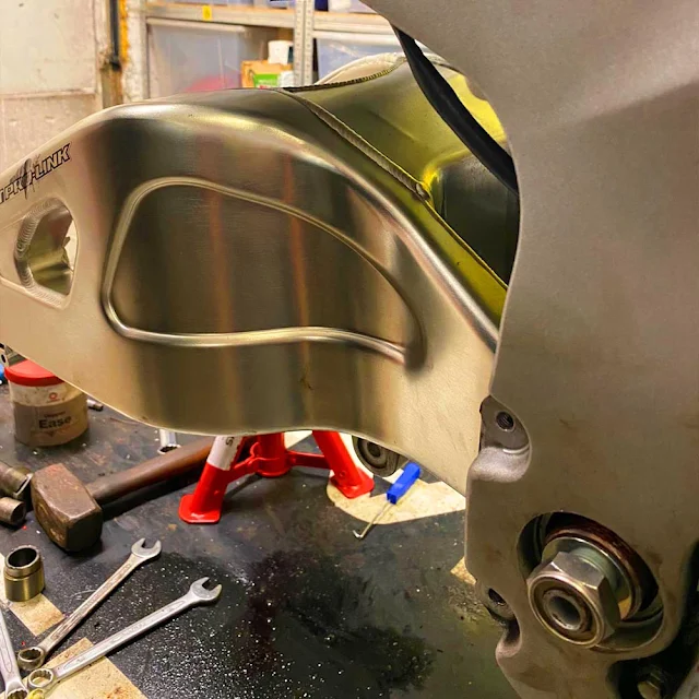
Apparently this is a desirable modification in the SP community as the SP2 swing-arm features a cutout to allow the fitting of factory race style 2:1:2 under-seat exhaust system. However the swing-arm isn't a direct replacement and there is some controversy about how the conversion should be carried out.

The main difference between the two swing-arms (apart from the cutout) is that the SP1 has a (nominally) 25 mm pivot bolt and the SP2 surprisingly uses a smaller (nominally) 20 mm bolt. The pivot bolt on the SP1 passes through a (nominally) 25 mm bore in the back of the motor where presumably it gains some extra rigidity due to the relatively tight fit between the pivot bolt and the hole through which it passes. Fitting the 20 mm pivot through the 25 mm hole will obviously not pick up any additional rigidity and this is where the controversy lies.

It would be nice to be able to say without ambiguity that passing a 25 mm pivot through a 25 mm bore would provide X amount of additional stiffness but I'm not in a position to do this 'cos I just don't know. But utilising MERCENARY logic here for a minute, if chassis stiffness is your thing, don't go reducing the size of one of the two joints in your motorcycle (the other being the steering head). Just sayin'...
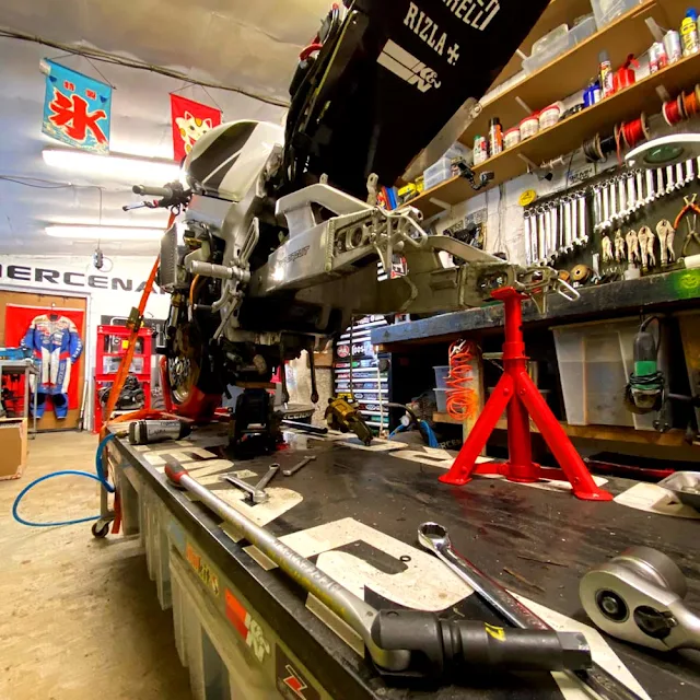

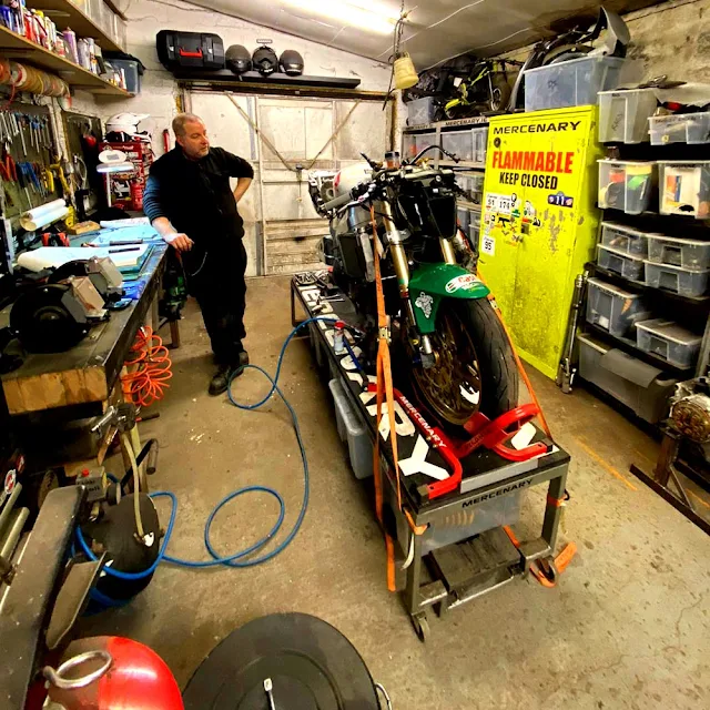
We're all about health and safety here at MERCENARY. The bike is secured in a front-wheel stand and strapped to the bench with ratchet straps. There is a small hydraulic car jack under the motor supporting most of the weight of the bike, but even if this loses pressure over time, the bike can't go anywhere. The axle-stand is just supporting the weight of the swing-arm.


That being said, there are three competing theories among the SP community on how to do this conversion.

The first theory is, just fit the 20 mm pivot and and the various other SP2 parts required and don't worry about the mismatch between the pivot and the bore. In the absence of data to the contrary, here at MERCENARY we think that seems legit.

Theory two is, have an engineer make up two sleeves with flanges at one end, the outside diameter being an interference fit with the hole in the motor, and the inner diameter being a clearance fit with the pivot, and the length being half the width of the crankcase plus the thickness of the flange. The idea being that one sleeve is pressed into the crankcase from each side and the flanges will help to locate the sleeves laterally.

And theory three is to just use one long sleeve that is an interference fit in the bore of the motor and a clearance fit with the pivot, and passes right through the motor from side to side.

I hope all that makes sense. This was the problem as presented to me and I was asked what I thought.

So working from the assumption* that passing the nominally 20 mm pivot through a nominally 20 mm hole will mitigate against the loss of chassis rigidity in this case, here's what happened...

Before any measurements could be taken and and an attempt a solution made, the SP1 swing-arm had to be removed and this turned out to be non-trivial.

As far as twenty year old motorcycles go, this one was exceptionally clean and has never been used in the wet. However, HRC saw fit to assemble the swing-arm system dry and it took a series of escalating techniques to remove the swing-arm pivot. The swing-arm pivot castellated lock-nuts were removed without difficulty using the correct 45 mm tool. However, getting the swing-arm pivot to move required loosening of the pinch bolts at the rear of the motor, the application of heat to the swing-arm bushes, blessing the whole lot with WD40, and unscrewing the pivot bolt with a 600 mm breaker bar with a impact Allen driver while simultaneously hammering on a specially fabricated steel drift with a lump hammer. It was much more difficult than was expected, the problem being that the swing-arm bushes had seized to the pivot bolt. 
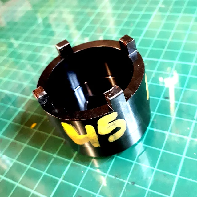

The castellated locknuts on the pivot bolt were easily removed using the correct 45 mm tool, but after that it got difficult...


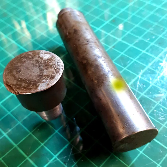
A drift was fabricated to protect the SP1 pivot bolt from the carnage about to be unleashed.
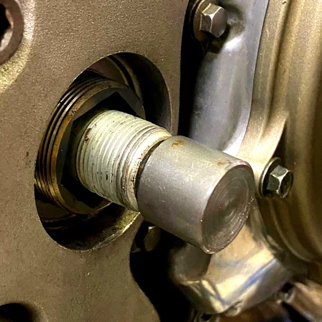


The drift in situ, pre-carnage.The drift in situ, waiting to have its head bashed in..
The drift in situ, waiting to have its head bashed in.


And the remains of the drifts after the SP1 pivot bolt has been removed.

Once the swing-arm was out the various bits were examined and measured using a telescopic bore gauge and a Moore & Wright 0-25 mm Micrometer with a resolution of 0.01 mm. That's 1/100th of a millimetre. That's pretty small and at that scale, there is variation in dimension depending on where the dimension is taken, so things have to be averaged out.
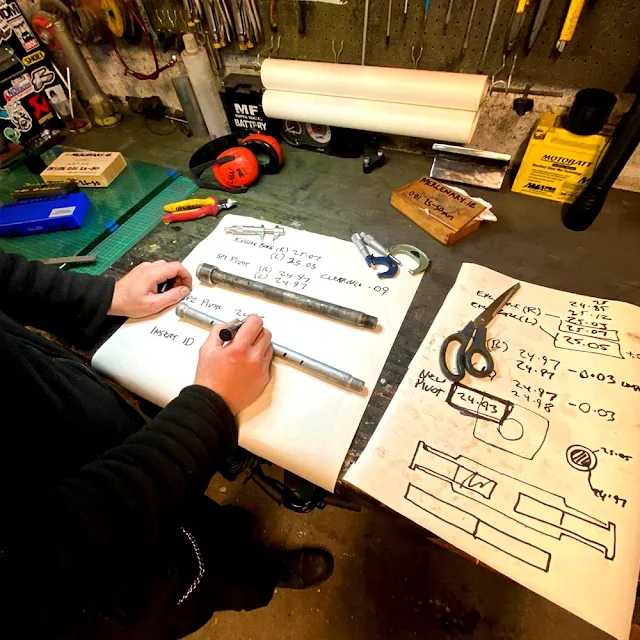

Dimensions and calculations.


So the nominally 25 mm SP1 pivot averaged out at diameter 24.93 mm.

And the nominally 25 mm bores on either side of the motor came out at diameter 25.03 mm.

This results in a clearance of 0.1 mm - 1/10th of a mm. This, in engineering terms, is a Sliding Fit.

If you think about it, this makes sense. The pivot bolt is tight enough in the bore that it can't rattle about, but it's not so tight that it has to be forced - it should slide in and out without difficulty. 

There was something else that turned up in the inspection. The bore in the rear of the motor is not a nominal 25 mm for the whole width. The first 38 mm on either side are machined to a nominal 25 mm, but the middle section is a cast finish, wider by a millimetre or two.

So remember the theories outlined above?

Well, Theory 2 with the flanged sleeves is a bust. Firstly because there is no need for the sleeves to be longer than 38 mm and secondly, although a flange could be used on the left side without problem, fitting a flange on the right side will force the swing-arm off center to the right by the thickness of the flange. And in any case, because the two pieces have to be a press fit which will hold itself in place anyway, the flanges don't really serve a purpose.

And Theory 3 with the single long sleeve? This is fine as far as the theory goes, but with the equipment available, it wasn't possible to make a sleeve 160 mm long with a center bore accurate to 0.01 mm. It is possible to manufacture such a piece, it's just I can't do it in-house. 

And there is an easier way...

But first, let's talk about Press Fits. We've already mentioned Sliding Fits and a Press Fit is kind of the opposite of that. A Press fit is when the shaft has a larger diameter than the bore in which it fits. Obviously there are caveats with this. The shaft can't be so big that it will break or permanently deform the part with the hole, and back in the real world, it must be able to be fitted using a realistic amount of force.

So we know the nominally 25 mm bore in the SP1 motor was actually 25.03 mm, so we want a sleeve with an outside diameter that's bigger than this. But by how much?

Fortunately the ISO 286 specification document has your back here...

ISO 286 reveals that a nominally 25 mm shaft, for a press fit has a dimension between 25.022 and 25.035. But this didn't seem right given the actual dimension of the bore, so the outside diameter of the sleeve was upped to 25.07 for an interference fit of about 0.04.

So that's the outside diameter. What about the inside diameter?
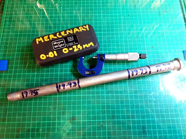

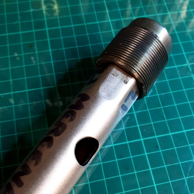
The SP2 pivot bolt showing the differences in diameter.

Well, the new SP2 sleeve has a nominal diameter of 20 mm, but measuring it revealed a maximum diameter of 19.95.

Remember the clearance of the SP1 pivot in the SP1 bore was 0.1 mm?

And remember that the whole point of this exercise was to reduce the drop in rigidity caused by using the smaller pivot?

It was decided to halve the clearance between the new SP2 pivot and the sleeve to 0.05 mm, which should still provide a Sliding Fit between the pivot and the sleeve. So pivot diameter of 19.95 mm plus clearance of 0.05 mm gives an Inside Diameter of 20.00 mm.

To reiterate this, the SP1 pivot had a clearance of 0.1 mm. That's 0.05 all around. The new clearance for the new SP2 pivot is 0.05 mm. That's 0.025 mm all around.

So, two sleeves, OD 25.07 mm, ID 20.00 mm and length 38 mm were turned on the lathe.
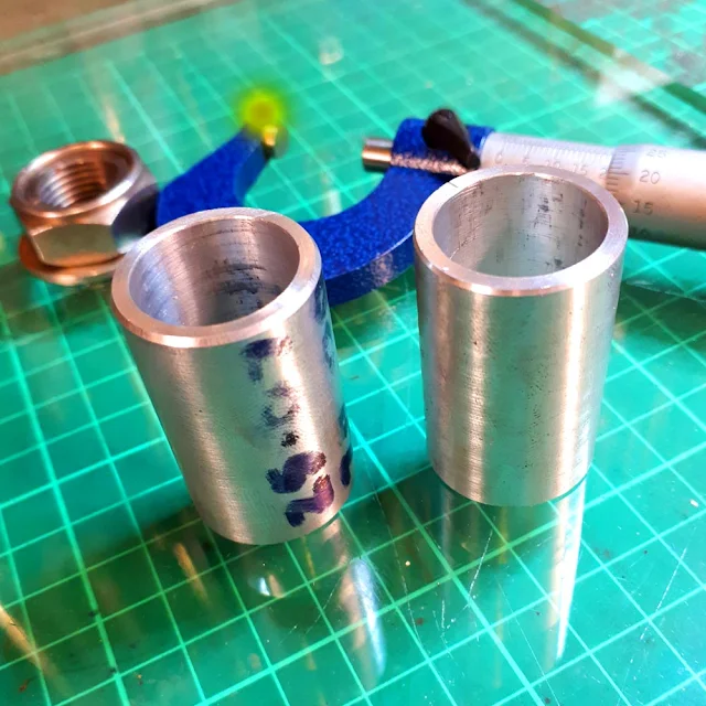

Two sleeves, OD 25.07 mm, ID 20.00 mm and length 38 mm were turned on the lathe.

So once the sleeves were made, they had to be pressed into the bores in the back of the motor. This was complicated slightly because the motor was still in the frame, and the sleeves had to pass through the holes in the sides of the frame.
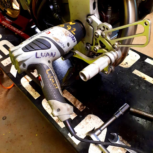

The bores in the back of the motor were heated prior to installation of the sleeves. Conveniently the holes in the frame were a snug fit for the heat-gun.

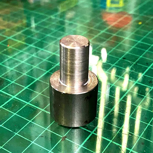
In order to install the sleeves in a controlled manner, a tool was fabricated using some M10 threaded bar, some M10 nuts and some parts turned on the lathe to ensure that the sleeves went in straight and only to the depth required.
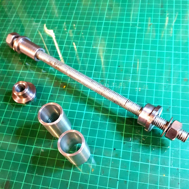
A tool was fabricated to install the sleeves in a controlled manner.


And because here at MERCENARY we believe that if a thing is worth doing, it's worth overdoing, everything was cleaned thoroughly with acetone and Bearing Lock applied to the sleeves and bores. Using the fabricated tool, the installation of the sleeves was simple and uneventful.
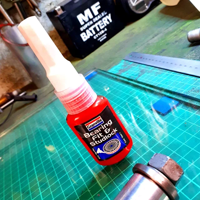

Granville Bearing Fit and Stud Lock.
Granville Bearing Fit and Stud Lock. 

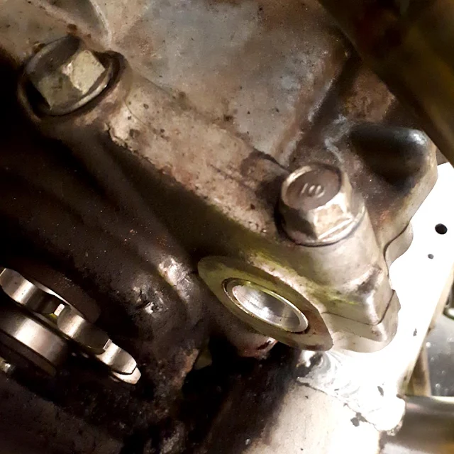
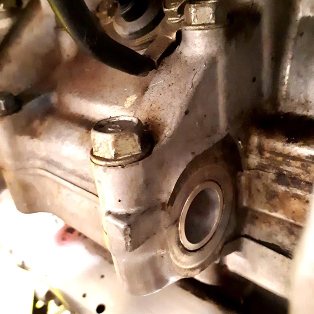
Left sleeve in situ. The sleeve is a press fit in the bore so it can't move, but bearing lock was used because why not.


Right Sleeve in situ in the rear of the motor.


Even though HRC assembled the swingarm dry, at MERCENARY that's not how we roll. Everything was liberally slathered with Copper Anti-seize during reassembly. Reassembly went ahead without difficulty and with only one thing to note. The adjuster nuts that hold the swing-arm into the pivot resemble giant grub-screws and require unusually sized hex head (Allen) drivers. It was found that the outside of 16 mm and 21 mm box wrenches were a good enough fit to be used instead of buying the correct tools from Honda.
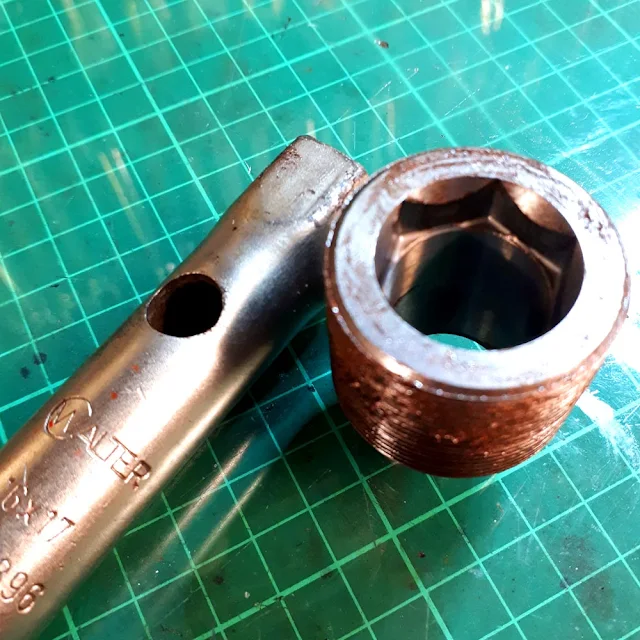
A 16 mm box wrench was used on the SP2 Adjusters instead of the obscure Allen key that Honda intended. Note the copper anti-seize paste on the adjuster nut.
A 16 mm box wrench was used on the SP2 adjusters instead of the obscure Allen key that Honda intended. Note the copper anti-seize paste on the adjuster nut.


And a 21 mm box wrench worked on the SP1 adjuster nuts.

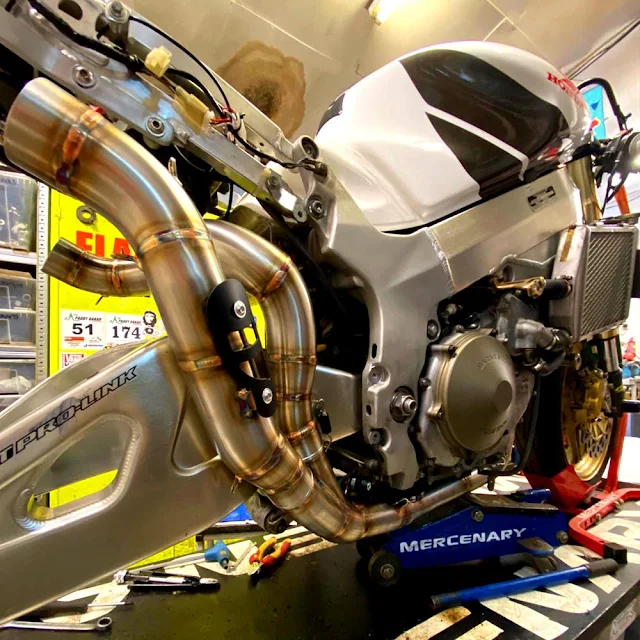
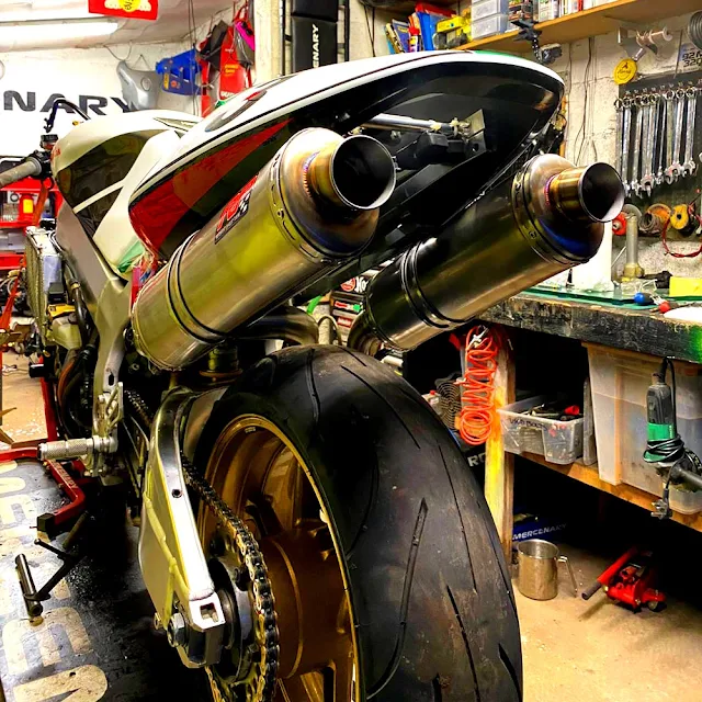
Once the new swing-arm was installed, the bike was fitted with a new 2:1:2 under-seat exhaust system that required some slight modification of the seat unit. It was decided to constrain the modifications to the horizontal parts of the underside of the seat unit rather than modifying the sloped part where the cut outs would be more easily seen. This required the milling of portions of the exhaust hanger washers so as not to put the seat unit under stress.
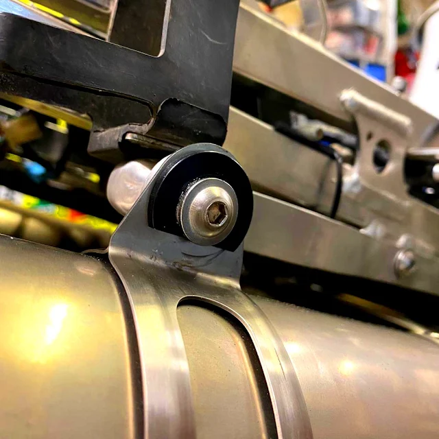
ExhaThe exhaust hanger washers were machined to allow clearance for the bodywork.ust Hanger Washers were machined to allow clearance for the bodywork.
The exhaust hanger washers were machined to allow clearance for the bodywork.

The rest of the reassembly/install went without incident.
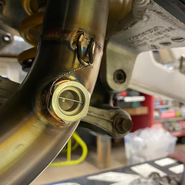

Some lock-wiring. MERCENARY never misses an opportunity to install lock-wire.


The SP2 swing-arm with the cut-out to allow fitment of the racing style under-seat exhaust.


Look at those curves! Just look at them!


The under-seat exhaust with the bodywork in situ.


Tired now.
Tired now.


*I don't know for a fact that it does and I have no easy, objective way to find out. But it could be done experimentally by holding the head-stock of the frame in a fixture and bolting a long bar into the swing-arm in place of the axle bolt. Then applying a given force to the end of that bar, first with the SP2 components with no sleeves, and then with the sleeves in place and measuring the deflection in the bar for both cases. But that was beyond the scope of this project.


Images Ro and Lunar


#VTR1000SP1 #VTR1000 #SP1 #SP2 #Honda #HondaSP1 #HondaVTR #HondaRC51 #RC51 #SwingArmConversion #SP2SwingArm #Mercenary #MercenaryMotorcycles #MercenaryMotorcycleWorkshop #MercenaryGarage


Sunday, 22 November 2020

SP1 Swingarm Conversion

Details to follow once the conversion is complete.

Here - https://www.mercenary.ie/2020/12/honda-vtr1000-sp1-to-sp2-swing-arm.html


Honda SP1 Swingarm Conversion - Mercenary Garage Motorcycle Workshop - Image Ro Hickey


Image Ro Hickey


#VTR1000SP1 #VTR1000 #SP1 #SP2 #Honda #HondaSP1 #HondaVTR #HondaRC51 #RC51 #SwingArmConversion #SP2SwingArm #Mercenary #MercenaryGarage

Saturday, 19 September 2020

Tool Chest

MotoReaper Tool Chest by Nelson Tai

MotoReaper Tool Chest by Nelson Tai

MotoReaper Tool Chest by Nelson Tai

MotoReaper Tool Chest by Nelson Tai

Images Nelson Tai


#NelsonTai #MotoReaper #RideDie #Cyberpunk #ToolChest #ToolStack #ToolBox #Mercenary #MercenaryGarage

Wednesday, 2 September 2020

Mercenary Social Media

MERCENARY is on Instagram.

That's not really news, MERCENARY has been on Instagram for quite a while but like most other social media, never really took it all that seriously.

But given the way the world has gone in the last couple of years, and the way social media has exacerbated the world's problems, MERCENARY is opting out of some social media platforms. 

In short, fuck Facebook. And fuck Twitter. Every time I go on Facebook there is some bullshit waiting to irritate me so I make changes and it finds new ways to aggravate me. That's not a bug, that's a feature. So fuck you Facebook, I'm out.

MERCENARY has permanently deactivated its Twitter account and will be making a strategic withdrawal from Facebook over the next week or so. 

If you are one of those people who follows us on Facebook and visits this blog by clicking through posts, you won't be able to that soon. We hope you will stay with us here, maybe by bookmarking https://www.mercenary.ie/

Or like I say, MERCENARY is on Instagram - https://www.instagram.com/mercenary_garage/


I made this simple tool to crimp battery cables in the shop press. Then I decided to paint it to make it more difficult to lose. Then after I used it for the first time I decided to paint eyes on it 'cos sometimes I'm fucking hilarious.

Marking out a regulator/rectifier mount for the Superlight 1000DS project. The regulators on the SL and the DS are the same external dimensions but the SL uses a steel adapter to fix to the frame. The adapter weighs about 100 grams so I thought about remaking the it in aluminium but decided instead to delete it altogether and make a tab to bolt it directly to the frame.

I was gifted this gearknob in the early noughties for a Baja Bug that I was building. The Baja got sold on before it was completed and at some point the gearknob found a new purpose in life. Or death, so to speak.

The collective noun for titanium bolts is a 'Fortune'. This is a fortune of titanium bolts, originally destined for the Fantic project and now redirected to the Superlight 1000 DS. The Fantic project hasn't been abandoned, just postponed.

I found this enormous fuse in the 1000 DS wiring loom and burst out laughing. It reminded me of those giant Smarties and Kit-Kats that appeared a while back.

The throttle bodies off the DS motor. I dismantled and cleaned them and replaced the fasteners with stainless ones. Then subsequently replaced the stainless with titanium and the two threaded bars the hold them together with aluminium ones. I think I saved about 50 grams. Maybe 40.

This was the world's skankiest Superlight 900SL when I bought it in 2004. It almost certainly still is. I've spent the last 16 years making it lighter but never really addressed the skank. It's undergoing a rebuild with a 1000DS motor and another weight loss program. Watch this space...

Ducati Superlight 900SL Mk.I #474 top yoke - The Multistrada igniton barrel bolt's up but is very heavy so it probably won't be there at the other end of this project.

This is where MERCENARY stores its essential fluids. One for petrol, one for diesel and a matte black one for Drakar Noir.

More tool chest stickers.

Vintage African Ivory Lucky Frog has found a new purpose as a tool chest knob.

The workshop empty and (fairly) clean for the first time in about four or five years.


#FuckFacebook #FuckTwitter #SocialMediaPolicy #Apocalypse2020 #Mercenary #MercenaryGarage